
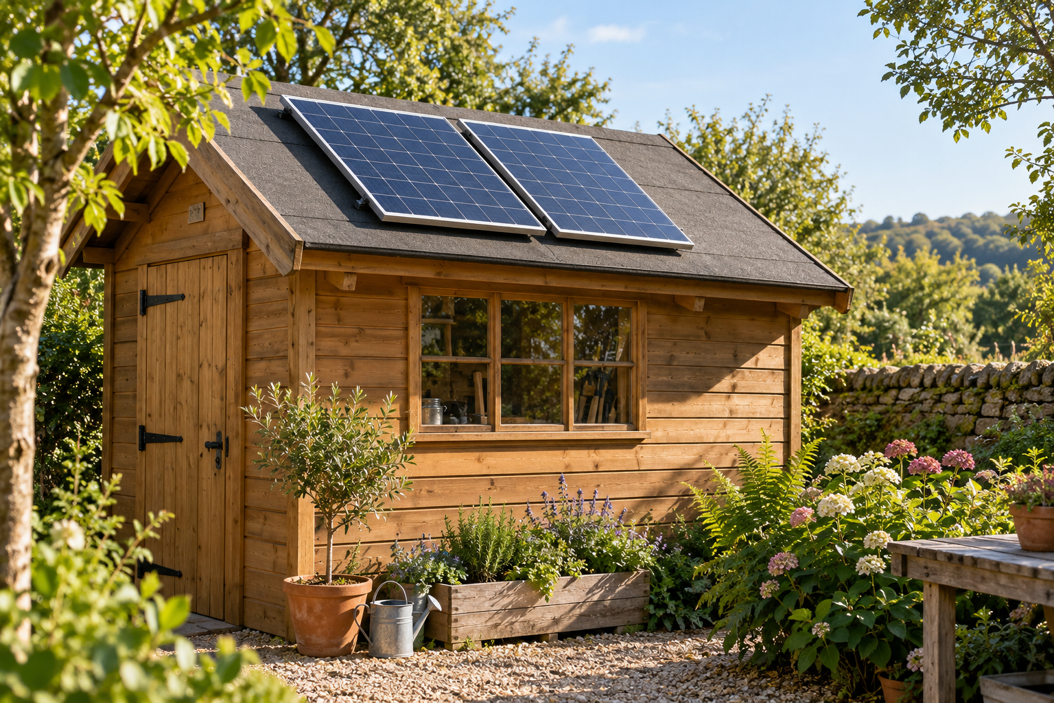
Two solar panels can be joined in different ways, even when they are powering the same small shed or cabin. One arrangement raises the voltage. Another raises the current. Neither creates extra sunshine, and neither is automatically the better choice.
The short answer: series often suits matching, unshaded panels feeding a compatible MPPT controller, particularly over a longer cable run. Parallel can suit a short run, some PWM systems and certain uneven-shading situations. The right choice must fit the controller’s voltage and current limits, the battery and the actual panels.
Series and parallel, in plain English
Voltage, measured in volts (V), is the electrical push. Current, measured in amps (A), is the flow. Power, measured in watts (W), is voltage multiplied by current. Think of these as three different measurements, rather than interchangeable descriptions of panel size.
In series, panels form one electrical string: the positive terminal of one connects to the negative terminal of the next. With identical panels under the same conditions, their voltages add while the string current is approximately that of one panel.
In parallel, positive terminals join the positive side and negative terminals join the negative side. With identical panels, the voltage stays approximately the same while the currents add. These are principles for comparing designs; the final connections, protection and isolation need a properly specified installation.
A two-panel example: the same watts, different delivery
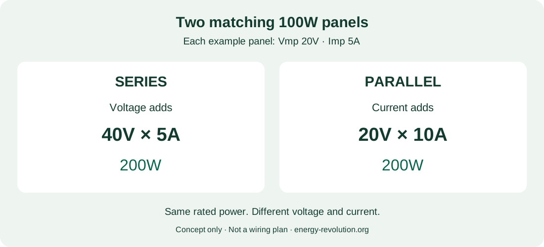
Imagine two matching 100W panels. Each has a maximum-power voltage, or Vmp, of 20V and a maximum-power current, or Imp, of 5A. These are deliberately simple example specifications, not specifications for a product linked on this website.
| Arrangement | Example Vmp | Example Imp | Rated total |
|---|---|---|---|
| One panel | 20V | 5A | 100W |
| Two in series | 40V | 5A | 200W |
| Two in parallel | 20V | 10A | 200W |
Both two-panel arrangements have the same 200W nameplate total. Actual output changes with sunlight, temperature, shade and system losses. Reconnecting panels cannot turn a 200W array into a 400W array.
Start with the controller, not the connectors
An MPPT controller can convert a suitable higher panel voltage into the lower voltage needed to charge a battery. A PWM controller generally operates the panels near battery voltage and requires a correctly matched array. A higher-voltage series string is therefore not a universal upgrade for a PWM system.
MPPT does not mean unlimited voltage, unlimited current or guaranteed compatibility. Read the exact model’s manual. Check its supported battery voltages, maximum PV open-circuit voltage, permitted PV short-circuit current, operating range, start-up requirements, allowable array power and battery-side charging current.
A portable power station normally has its own solar controller. Use its solar-input specifications rather than adding an external controller unless its manufacturer explicitly supports that arrangement. A plug that physically fits does not establish electrical compatibility.
The battery voltage and panel voltage are also different things. A “12V” panel is a nominal category, not a promise that it produces exactly 12V. Do not infer a 48V battery requirement from a drawing showing panels in series.
Cold weather can push series voltage too high
Voc means open-circuit voltage: the panel’s voltage when no current is being drawn. It is higher than Vmp. Series design must consider the combined Voc at the lowest expected temperature, not just the working voltage on a mild afternoon.
Here is a simplified calculation. Suppose each example panel has Voc of 24V and a Voc temperature coefficient of −0.30% per °C. At a cell temperature of −10°C, the difference from the standard 25°C reference is 35°C. The estimated rise is 35 × 0.30% = 10.5%.
- One panel: 24 × 1.105 = 26.52V.
- Two in series: 2 × 26.52 = 53.04V.
- Three in series: 3 × 26.52 = 79.56V.
That illustrative three-panel string would exceed a controller with a 75V absolute PV limit, although its 25°C Voc totals only 72V. A current-limiting feature cannot make excessive input voltage safe. Use the real datasheet, local design temperature, tolerances and manufacturer’s sizing method; do not design right against a limit.
Hot panels create the opposite planning issue: operating voltage falls. The array must still provide enough voltage for charging, including controller headroom and cable drop. Our guide to a solar battery not charging in cold weather covers another separate issue: the battery’s own charging-temperature restrictions.
Why series can help with a longer cable run
For a given cable resistance, heating loss is current squared multiplied by resistance: P = I²R. A higher-voltage array delivering the same power at lower current can therefore lose less energy along its shared cable run.
Take the two-panel example and assume the outgoing and returning cable together have 0.20 ohms resistance. At 5A, the illustrative loss is 5 × 5 × 0.20 = 5W. At 10A, it becomes 10 × 10 × 0.20 = 20W. Voltage drop would be 1V and 2V respectively.
These are fixed-current teaching calculations, not predictions of a real controller’s operating point or a cable-sizing recommendation. Cable size must also satisfy current capacity, installation conditions, temperature, protection and acceptable voltage drop. Series does not justify using any thin cable that happens to be available.
Does parallel work better in shade?
Sometimes, but “parallel solves shading” is too broad. A shaded panel can restrict a series string. Bypass diodes can allow current around affected cell groups, usually sacrificing some voltage and power. The result depends on which cells are shaded, the panel layout and the controller’s tracking behaviour.
Parallel branches can let an unshaded panel contribute without carrying exactly the same current as its shaded neighbour. However, the branches share a voltage, shaded panels still lose output, and there must be enough voltage for the controller to charge the battery.
A moving strip of tree shade is different from one whole panel being shaded for hours. Panels facing substantially different directions may justify separate MPPT trackers or controllers, designed to work with the same battery system. First investigate whether you can move the panels out of shade. Our shaded-shed solar guide helps you assess the location.
Four panels: a mixed arrangement may fit
With four of the example 100W panels, two identical series strings connected in parallel would give approximately 40V at 10A, or 400W at their rated maximum-power point. This is often written 2S2P: two in series, with two strings in parallel.
That arithmetic does not approve the design. Each string needs the same suitable operating-voltage characteristics. The controller must accept the cold-weather string Voc and combined short-circuit current. Connectors, branch wiring and any required string protection must be specified for the arrangement.
Mixing an old panel with a new one needs more than matching the wattage printed on the front. In series, current mismatch matters; in parallel, voltage mismatch matters. Check Vmp, Imp, Voc, Isc and the manufacturer’s instructions. Separate controllers may be more practical than forcing unlike panels together.
Three small-system situations
- Two matching panels beside an unshaded shed: compare both arrangements against the MPPT manual. Series may offer useful voltage headroom; parallel may also be valid. A short cable run reduces the importance of the cable-loss difference.
- Panels farther from a cabin: series can be attractive for reducing array-cable current, provided cold Voc remains safely within the equipment limit and the installation is properly designed.
- A compact PWM lighting system: preserve the manufacturer’s specified panel and battery combination. Do not join panels in series simply because a larger MPPT installation uses that layout.
If your real problem is running out of stored energy after sunset, changing wiring alone may achieve little. Start with whether your shed needs more panels or more battery capacity.
What to check before buying extra equipment
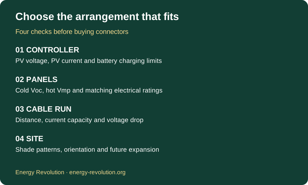
Write down panel model numbers and electrical ratings, controller model, battery voltage and chemistry, cable distance, likely minimum temperature and shading pattern. Ask the supplier or installer to confirm a complete configuration, including protection and future expansion.
PV input current and battery charging current are not the same. For illustration, 200W delivered through a controller at an assumed 95% efficiency into a battery charging at 14V is about 13.6A: 200 × 0.95 ÷ 14. A 5A series-panel current does not imply a 5A battery cable requirement.
Our Recommended Products page includes small solar kits and portable power stations to explore. Check the current manufacturer’s specifications before pairing any of them with additional panels. A complete kit is not automatically expandable, and our example numbers do not certify those products.
Connections and protection deserve proper attention
Panels produce voltage in daylight, even with the battery disconnected. Never unplug PV connectors under load. Use the manufacturer’s isolation procedure and a competent installer where you cannot establish a safe working method.
Use correctly rated PV cable and manufacturer-approved mating connector pairs. “MC4 compatible” wording alone does not prove that different brands may safely be plugged together. Parallel arrays also need assessment of possible reverse current and string fusing against the module’s ratings; branch connectors are not protective devices.
Battery circuits need appropriately located overcurrent protection, and DC isolation equipment must suit its duty. Do not treat this comparison or a Pinterest illustration as a finished wiring plan.
Frequently asked questions
Which arrangement produces more electricity?
Neither inherently increases the panels’ rated total. Usable energy depends on controller compatibility, cable losses, shade, weather and the battery’s ability to accept charging.
Can I connect panels directly to a battery?
Use a suitable charge controller or an approved integrated system. Direct connection can result in uncontrolled charging and equipment damage.
Is parallel always safer?
Lower voltage does not remove electrical risk. Parallel raises available current and can introduce reverse-current paths. Both arrangements require suitable protection and installation.
Can I change the arrangement later?
Possibly, after recalculating the complete design. Recheck both voltage and current limits, protection and connectors before any changes, using the specified isolation procedure.
Sources and further reading
Manufacturer guidance checked on 26 October 2026. Always consult the manual for your own equipment.
- Victron: PV array configuration and temperature checks.
- Morningstar: PWM and MPPT controllers.
- Victron: shading, bypass diodes and panel voltage.
- Stäubli: avoiding incompatible connector combinations.
- Stäubli: connector safety instructions.
Plan the whole system before choosing the wiring
Choose the arrangement that meets every equipment limit and suits your site. The useful goal is dependable charging for your actual loads, rather than the highest voltage or the most impressive-looking array.
For more beginner-friendly planning ideas, explore our DIY Alternative Energy Projects bundle. It supports project planning; it does not replace product manuals or professional electrical design.
Explore the Energy Revolution offer
Affiliate offer: assess the seller’s claims, terms and suitability independently. We do not guarantee its results.